Some time ago, I was challenged with a project for automatically monitoring the occupancy of a natural area.

The idea was to use a drone equipped with a camera to shoot a video from the air. The video would be later processed with computer vision algorithms and deep neural network models to obtain the number of people present at the site at the time of recording.

It involved a linear area several kilometers long, which the drone would survey from end to end, with the camera capturing the full width of the path as it moved along.

The expected result was a video with bounding boxes overlaid over each detected person, along with a global counter showing the total number of people seen up to that point.

Once the video was processed, the detected occupancy would be reported to the authorities, who would compare it with manual counts to detect anomalies caused by large variations.

To make things more interesting, we couldn’t count on good-reliable and high-bandwidth internet access in the area to be surveyed, so the only viable option was to process the video completely offline. Also, deploying the solution in the cloud would be more complex and require the usual monitoring and management.

So, we’re talking about a multi-object tracker. This is usually done in two steps:

1. Detection

In the detection phase, we run inference on a video frame using a deep CNN. The result is a set of bounding boxes, each with its class (type of detected object) and a confidence score ranging from 0 to 1.

Image of an office with bounding boxes over different objects
Photo by MTheller

2. Tracking

In the tracking phase, we assign a unique identifier to each bounding box and maintain it across consecutive frames. We analyze the content of the bounding box in the previous frame and compare it with the current one to determine if it’s the same object. When a new person appears who hasn’t been detected previously, we increment the global people counter. This a way to avoid counting the same person once per frame. A good tracker should also be able to handle temporary occlusions. For example, if a person walks behind a tree and gets occluded temporarily, when they are visible again, the tracker must recognize it’s the same person seen in previous frames and reassign the same id, which is called re-identification.

GIF animation of a multi object tracker
Image from GeekAlexis‘s github page
Tracked people with their corresponding unique IDs

Hardware

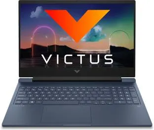
To execute this process on-site, a modest gaming laptop by the standards of that time was purchased. An HP Victus with 16 GB of RAM, a 512 GB SSD, and an Nvidia RTX 3050 graphics card.

HP Victus laptop

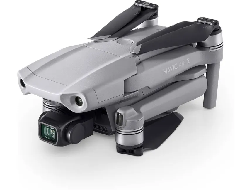
To capture the footage, a DJI Mavic Air 2 drone was used, recording at 4K resolution (3840×2160).

DJI Mavic 2 Air Drone

Software

The operating system is Windows. I would have preferred to install a Linux distro, but my experience with laptops using dual GPU setups is a bit hit-and-miss. I use Linux as my daily driver on one of those machines—I know what I’m talking about 😄. And I didn’t have much time for development, so I prioritized having good driver support, even if it meant doing some acrobatics to get the whole framework working.

PREPARATION
In previous years, the company already did people counting on beaches using a custom solution, developed several years earlier based on a YOLO v4 detector + the Deep SORT algorithm.

Still image of a video where people counting is showcased
Frame produced by the preexisting solution. Notice the unique numeric IDs on top of each bounding box. Blue boxes are new detections (no ID yet), while red boxes are detections tracked over time.

YOLO is a family of detection algorithms known for their high performance by doing a single pass through the neural network (You Only Look Once).

The bounding boxes generated by YOLO in the current frame were fed to Deep SORT for tracking.

Deep SORT stands for Deep Simple Online Realtime Tracking. It relies on deep learning models and computationally complex algorithms for bounding box association. A CNN extracts appearance descriptors that encode the appearance of the detected objects. A Kalman filter is also used to predict the state of the object in the current frame based on its last known state, accounting for the object’s motion dynamics.

The process ran in the cloud using servers with Nvidia A100 cards. An RTSP stream was transmitted live, stored on the server, and added to a job queue.

It worked but had some shortcomings:

  • There was no way to resume a stream if it was cut off, which happened frequently on the beach due to high crowds and cell saturation. An incomplete video was processed anyway, yielding a partial result.
  • It was very heavy: It could take 30 minutes from the end of a transmission to having the result ready. This was to be expected because of Deep SORT’s high complexity
  • It got expensive very quickly: In order to save money, GCP instances had to be manually brought down and up every day. Arrive one minute late, and they’re out of GPUs for you to rent.
  • GPUS were sometimes pulled offline for some reason, and the instances had to be restarted manually.

When the preexisting solution was developed, a custom YOLOv4 model was trained for it, using hundreds of real images taken by the drone at beaches and manually labeled. Since the model worked well, and there was no time to train and tune a new one, I decided to reuse it but changing the framework and tracker, as the bottleneck was the detection stage, which could take over 1s per frame.

I researched ways to lighten the tracking workload to make it feasible to run offline on a laptop and found several interesting proposals with one thing in common: not running tracking on every frame, but on one out of every N frames.

Mvmed is a real-time online tracker for objects in MPEG-4 and H.264 compressed videos. The interesting part here is that the motion vectors stored in the P and B frames of an H.264 stream are averaged inside each bounding box to interpolate their positions and sizes for the frames between tracker executions.

As curious as this approach seemed to me, getting the Docker container to build was far from straightforward because of broken and outdated packages. It turned out to be a rabbithole I couldn’t afford to go down.

Also, Mvmed doesn’t use YOLOv4 for detection, so I would have had to change that part—which I wouldn’t have minded if the project compiled out-of-the-box.

FastMOT is another somewhat outdated project by current standards with the same approach but uses a KLT filter to fill in the gaps between tracking steps efficiently.

  • Detection is done with YOLOv4.
  • Tracking is run once every N frames using a DeepSORT algorithm with OSNet Re-identification. It also includes camera motion compensation.
  • Accuracy on the MOT20 training set is 77.9% when run every 5 frames.

So at that time, I decided to move forward with FastMOT.

After updating quite some obsolete dependencies, fixing many build errors, and compiling OpenCV with support for the RTX 3050 compute architecture (compute_85), I converted the detection model to ONNX in order to finally convert it to the TensorRT format FastMOT expects.

And I finally ran it on a test flight.

Static frame of a video with detection bounding boxes
Frame of a processed video showing only bounding boxes without ids

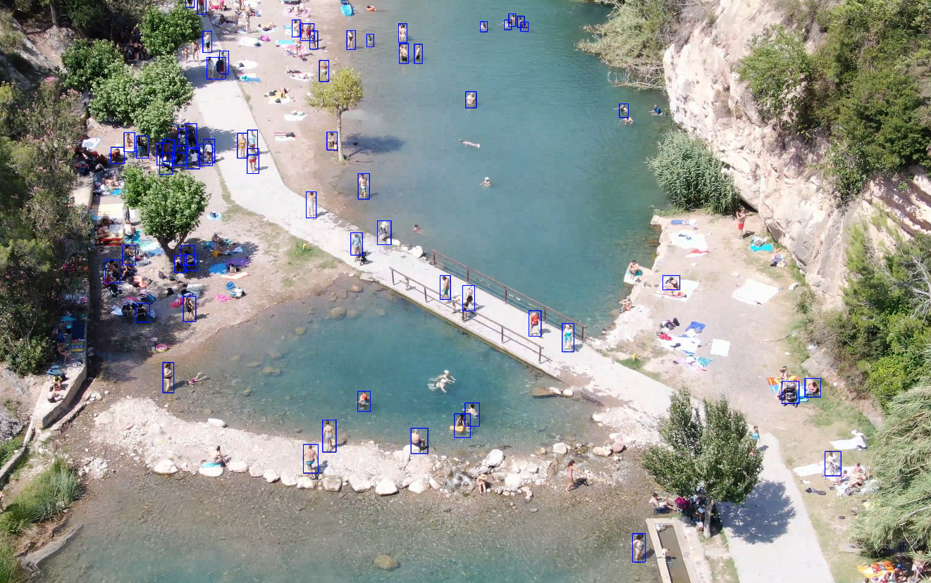
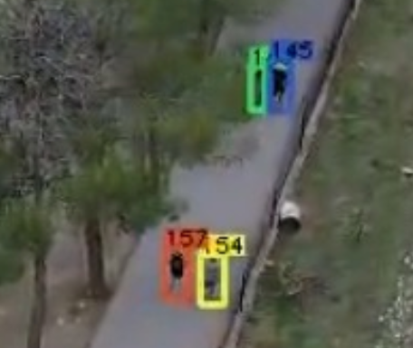
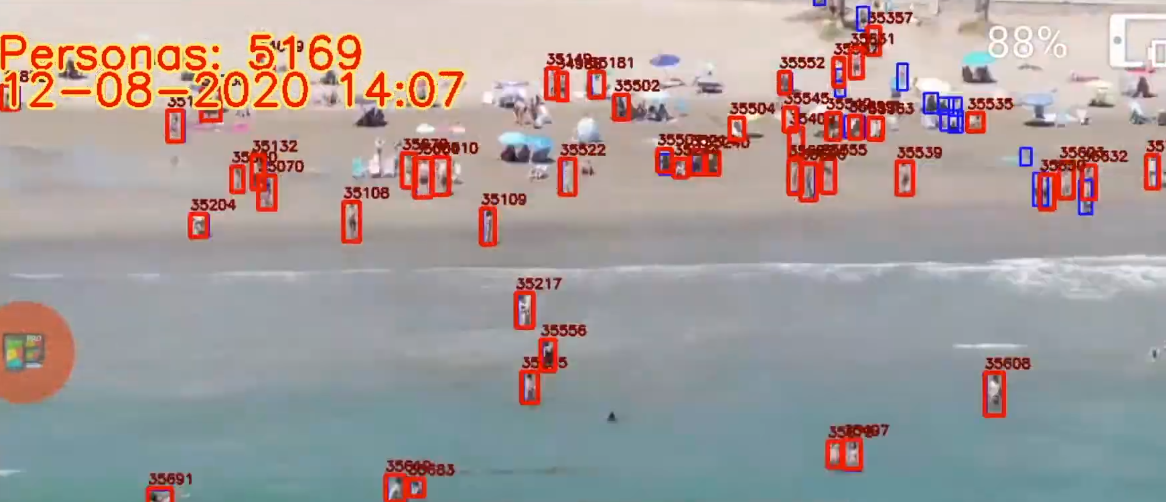
I modified the tracker code to add two counters and display them on each frame. One counter shows the number of distinct people counted so far, and the other shows the number of people detected in the current frame.

I tweaked the line and font sizes a bit, and this was the result.

GIF animation showing the results
Scaled down gif version of the processed video (10 fps)

Deployment

To run it on Windows, I used WSL2. Fortunately, GPU virtualization had recently been supported, so I installed the Nvidia Docker container toolkit.

I deployed the Docker container.

And to allow a user to run it easily, I programmed a simple Python UI using tkinter.

Image of the UI interface

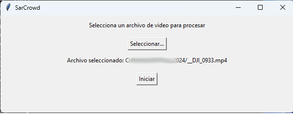
The UI runs locally (not in WSL), and lets users select a file and process it. When processing starts, the Docker container is launched this time in WSL with the proper parameters. The X11 windows are redirected, and a window shows the video being processed in real time.

docker run --gpus all --rm -it -v $(pwd):/usr/src/app/FastMOT -v $3:/tmp/data -v /tmp/.X11-unix:/tmp/.X11-unix -e DISPLAY=unix$DISPLAY -e TZ=$(cat /etc/timezone) fastmot:latest python ./app.py -i "/tmp/data/$1" -o "/tmp/data/$2" --mot -g -v
Window showing the results

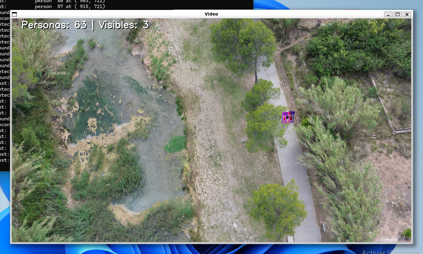
Finally, a desktop shortcut pointing to the Python UI app completes the setup.

  • It ran consistently at 30+ fps on the Victus laptop with frameskip (N) = 5 with considerably good re-identification results.
  • The confidence threshold for rejecting detections was set to 0.3 (objects detected with < 30% confidence are not passed on to the tracker)
  • The tracker works fairly well when the YOLO model struggles with detections in consecutive frames
  • The model is primarily trained over pedestrians captured from above with a drone. As you can see it struggles a bit with swimmers.

Final thoughts

The implemented solution fulfilled the expectations, and seemed to provide the right balance between precision and computational cost for running on edge hardware.

There are many other interesting architectures for dense crowd estimation I’d like to take out for a spin like CSRNet


Melbits Pod surrounded by Melbits

One of the things I enjoy the most is embedded development. I always say that creating something with your own hands, which you can also program and watch as the gadget comes to life, is an incredible feeling. Eight years ago, I embarked on what was possibly my most ambitious project in this area.

It all started way back in 2016 as a business idea to create something fun that would also have a positive impact on society.

The motivation

In this screen-filled world where children are increasingly immersed at an early age, and where parents often use them as a sort of “digital pacifier” to give themselves a moment of respite, we who are still big kids perceive that the art and joy of playing with physical toys in the real world is being lost. Audiovisual media floods all our senses, leaving little to no room for imagination.

Little girl using her smartphone in bed

Designed by FreePik

But don’t get me wrong, I am a big advocate of technology because it enables us to do incredible things and allows for lifestyles never seen before. In recent decades, we’ve experienced a technological explosion unlike anything in human history. Robotics, telecommunications, electronics, artificial intelligence… New technologies arise and become obsolete in just a matter of months. It’s hard to stay up to date, but it’s even harder for society to absorb this new world of possibilities moving at breakneck speed. So, in many cases, something that could be highly beneficial if used well becomes the opposite because it’s misused. And it’s misused because development has been so fast that we haven’t had time as a society to build a culture and healthy habits around the digital world.

From a reflection like this, an idea emerges.

The idea

In short: an electronic toy with sensors that you have to play with in order to progress in a digital game.

Melbits are small digital pixies that start their lives as seeds. As they grow and develop, they turn into puppies or adult Melbits. But not everything is happiness in the world of Melbits, because viruses, representing everything bad in the digital world, are lurking and can infect Melbits, thus creating new viruses.

The user will obtain Melbit seeds in the digital game (smartphone or tablet), which must then be transferred to the real world by loading them into the toy, which acts as a sort of incubator. Next, they’ll receive an incubation recipe which might include moving the toy, letting it stand still, give it some sunshine or maybe keep it in a dark, cold place.

This is where the digital part ends and the physical part begins. From this moment on, the user must play with the toy as instructed if they want the Melbit to develop correctly inside. Otherwise, a virus will appear, and there will be consequences.

Little girl playing with the Melbits Pod

The incubation process can last from seconds to hours, helping to cultivate skills like patience and perseverance.

Once incubation is complete, the toy notifies the user, and they can transfer the results back to the tablet to see how well or poorly they did.

Girl lifting up the Melbits Pod revealing a new Melbit inside


Hardware specs

Right from the beginning, it was clear that the toy needed to have sensors, some way to provide feedback to the user, and, if possible, no buttons, as well as the ability to communicate with a smartphone or tablet. However, the specific requirements evolved throughout the development process as we shaped the user experience and experimented with different solutions to find the one that offered the best cost-benefit ratio.

Here’s how the final specifications turned out:

  • Bluetooth Low Energy
  • 4 high-brightness orange LEDs
  • RGB LED
  • ERM vibration motor
  • Temperature sensor
  • 2 photodiodes
  • Accelerometer
  • Amplified speaker
  • Rechargeable lithium battery
  • USB port
  • Hidden multifunction button (not typically used)
  • ARM Cortex M0 microcontroller at 64 MHz
  • 192 KB of Flash memory
  • 24 KB of RAM
  • Internal hard ABS casing with screws, enclosed in a soft vinyl outer casing

Firmware Specs

  • Encrypted bootloader with OTA capability
  • Game logic
  • Music player with sine wave, triangular wave, noise, and PCM channels
  • Extra channel to control the vibration motor
  • Extra channels to control the LEDs
  • Several embedded melodies and effects
  • Adjustable output volume
  • Battery charge via USB connection and SoC monitoring with feedback
  • Sensor reading and updating
  • Motion pattern recognition
  • Automatic sleep and wake-up mode without buttons
  • “Box mode”
  • Storage memory
  • Customizable settings (vibration, LED brightness, speaker volume)
  • Streaming sensor readings via BLE
  • Diagnostic functions for manufacturing
  • Magic Link! (more on this later)
  • Proprietary encrypted BLE protocol controlling all functions
  • All of this within 192 KB of Flash and 24 KB of RAM!

Software Specs

The Melbits Pod app was developed in parallel by another team. It’s a Unity3D project which I adapted to support Bluetooth LE and async communications with the POD.

  • Cross-platform iOS/Android app
  • 3D graphics with skeletal models
  • Multiple props, accessories, and costumes
  • 2D touch UI
  • User guide tutorial
  • Melbit family tree
  • Persistent user profile
  • UI for viewing and changing toy settings
  • Tutorial voiceovers
  • Music and sounds by Aries!
  • Analytics
  • Activities with Melbits (playing, feeding, etc.)
  • Flow for loading and unloading a Melbit to/from the POD
  • Bluetooth Low Energy with proprietary encrypted protocol
  • Automatic toy firmware updates via OTA
  • Front camera usage to take a selfie with your Melbit
  • Augmented reality using the rear camera

Pod Simulator

  • Desktop app created during development to parallelize app development before hardware was available

In addition to all of this, I studied European and international regulations, as they are very strict with toys.

In closing

It was undoubtedly a great and exciting project. Join me in the following articles where I explain how I developed it prototype after prototype to the final product as the technical director of Melbot Studios, how I traveled to China to resolve questions with the manufacturer, and how it was finally mass-produced and went on sale after a successful Kickstarter campaign!

A few years ago I was playing rythm guitar in a small band along with three of my friends. One day, our lead guitarist spotted how useful a looper pedal could be to us, but he was unsure if the purchase was worth the price.

For those of you that are not familiar with this kind of gear, a looper pedal is a device that is daisy-chained between an electric guitar and the amp, recorder, or the rest of your gear. It’s able to record what you play and at some point play it back in the background while you play new stuff. It’s extremely useful where more guitars than available are needed. Usually it can be controlled by means of some footswitch, hence the ‘pedal’ denomination.

I remember that I was shocked of seeing looper pedals starting at $130. Soon, my engineering-obsessive mind started to think of ways of building a cheaper device without compromising quality.

🎯 Goals

I made a wishlist for a decent looper pedal features:

  • It should be able to start recording when I tap a switch.
  • It should be able to stop recording and play the loop back when I want.
  • It should allow me to add up more “layers” of sound on top of the existing loop.
  • I should be able to stop it whenever I want.
  • It must feature a decent sound quality.
  • I must stay under $50

Given this list of requirements, I decided to work on a design, and build a prototype.

💡 Ideas

Okay, two things were clear… I was going to need quite a big deal of RAM to store the audio, and a decent CODEC to DAC/ADC it.

Real-time audio streaming can become a relatively bandwidth-demanding task, so the RAM needed to be both fast and big enough.

In order to control de pedal I was going to need at least two buttons, but that was the smaller of my concerns.

🛠️ Tools of trade

For this prototype I was lucky to have an Altera DE1 training board I bought to play with FPGAs.

DE1

The board features an Altera Cyclone 2 FPGA, an 8-MByte SDRAM Chip and a WM8731 high-quality, 24-bit, sigma-delta audio encoder/decoder with minijack inputs/outputs.

The RAM is 16-bit wide, and the CODEC is 24-bit, so to achieve CD-Quality (44,100 Hz) the formula would be like:

44,100 Hz x 3 bytes = 132300 bytes per second, or 129 KBps

Then, is the RAM capable of handling that?

With SDRAMs you can R/W in a mode named Burst where you give the starting address and the number of words to read/write and then the words are read/written sequentially with no more overhead. Let’s do some calculations:

What is the minimum frequency needed to stream 24-bit audio@44,1KHz to/from the SDRAM?

A naive calculation would be:

  • 1 word = 16 bits = 2 bytes
  • We need to stream in 24-bit units, that would be 1.5 words, so let’s round it up to 2 words
  • That makes 176.4 Kbps or 88.2 Kwords per second
  • Let’s double it because the looper might be recording new data at the same time it’s playing the old one.
  • Ideally, a theoretical bandwidth of 176.4KHz would suffice, but in practice there is an overhead due to CAS/RAS strobe, the memory switching a page, etc…

This particular chip can run up to 133 Mhz, which yields far more than needed bandwidth. One problem solved 🙂

At this point it looked like everything boiled down to hooking up the SDRAM, the CODEC and some sort of footswitch.

🧑‍💻 Design

I came up with the following design:
architecture

The board has 2 XTALs, one running at 50MHz and another one running at 27 MHz.

– The SDRAM needs 100MHz, so one of the built-in PLLs in the FPGA was used to double the frequency of the 50MHz XTAL up to 100MHz.

– The audio CODEC streams data at 18.4MHz, so another PLL was used to reduce the 27MHz clock frequency down to 18.4.

  • The rest of the cores run at 50MHz

Let’s examine the rest of the modules I wrote in VHDL:

Reset delay

This module makes sure that every other module has been properly reset and that the PLLs are locked before the whole system starts operating.

Its inputs are just a signal from one of the on-board buttons that acts as a RESET button, the 50MHz clock and the ‘locked’ signals from the PLLs.

When the external reset is just deasserted, or the system is just powered on AND the PLLs are locked, it uses a register to count 3 million cycles of the 50MHz clock and then deasserts the internal reset signal used by the rest of the modules.

CODEC controller

It’s responsible for streaming data to and from the CODEC in I2S format. Its interface with the other modules are a couple of 16-bit busses for input/output streaming data, reset and a 18.4 Mhz clock from the Audio PLL.

I2C controller

The CODEC has a lot of configuration parameters (like gain, volume, input selection, audio format…) that you must configure using I2C@20KHz. This controller operates pretty much on its own and its only task is to send a sequence of predefined commands to configure the CODEC just after RESET. It’s written in Verilog and I grabbed it from the Altera demo cores that came with the board.

MFC (Memory Flow Controller)

This is one of the most complex modules of my looper.

It interfaces with the SDRAM through two FIFOs and is responsible of feeding the looper core with streaming data stored in the SDRAM and to write to the SDRAM data streamed from the looper core. Its interface with the other modules are a couple of 16-bit busses for I/O and a control bus for controlling and signaling these conditions:

  • Input fifo full (tristate)
  • Output fifo empty (tristate)
  • EOL (End Of Loop) (Core → MFC)
  • Busy (MFC → Core)
  • Start writer (MFC → Core)
  • Write enable (MFC → Core)
  • Read enable (MFC → Core)
  • Fifo clock (data in the busses is sync’d to this clock)
  • Reset and clock as usual

The core uses 3 23-bit registers to point to relevant memory addresses inside of the SDRAM:

  • Read address
  • Write address
  • End of loop pointer

The behavior is modeled by three VHDL state machine processes: ‘reader’, ‘writer’ and ‘EOL_marker’.

Reader: When streaming is activated it instructs the SDRAM controller to burst-read data starting at the Read address pointer. When the data is available it’s enqueued in the input FIFO and the Read pointer is incremented (since it’s 23-bit (addressing 8 Mb) it will naturally overflow to 0 when you run out of memory). If the input FIFO becomes full the SDRAM controller stops reading, if it becomes almost empty it starts reading again thus ensuring continuous uninterrupted streaming of audio. The looper core can read data from the input FIFO transparently through the input bus.

Writer: Operates exactly in reverse: It takes data from the output FIFO (enqueued by the looper core) and stores it in the SDRAM via the SDRAM controller starting at the address pointed to by the write pointer. When the FIFO becomes empty, the controller stops storing data. If it becomes almost full then it starts storing data again.

EOL_marker: When the EOL signal is asserted, it first flushes the Output FIFO and then sets the EOL pointer to the address being currently written (i.e: the Write pointer).

It also features a debug sine-wave writer to test the MFC and audio output.

The SDRAM controller is a very cool one I pulled off OpenCores.org. It’s a port of a Xilinx memory controller for a Spartan FPGA to the Altera Cyclone II (specifically for the memory in the DE1 board!). Its greatest features are:

  • Quite parametrisable
  • Features time slot-based dual port (I use one port for reading and the other one for writing).
    • It runs at 100MHz (130MHz was originally supported, but the port doesn’t work at that freq).– Interfaces with your core mostly like a SRAM (address bus, data bus and simple control bus).

Testing the MFC and CODEC

Once I had the MFC and CODEC up and running, I uploaded to the SDRAM a .wav file and then wrote a simple core to stream it through the MFC out to the CODEC to see if it plays back.

I plugged the board to a cheap guitar amp to hear it.

Keyboard controller

Since I needed fairly big keys to be able to control the core while I was playing guitar I opted by having a PS/2 keyboard on the floor and pressing the bigger and most accessible keys (Spacebar and Ctrl’s) with my foot. The DE1 board has a PS/2 port so I chose to use the PS/2 controller that comes with the board (written in Verilog).

With the keyboard you can assert a few commands:

  • Start recording
  • End of loop (the looper starts playing back what you played, but it doesn’t record what you play now).
  • End of loop, but start recording a new ‘layer’ of sound (This allows to overlay what you play now to what is being replayed by the looper).
  • Pause/resume layer recording
  • Pause/resume regular (no-layer) recording

I used a Logitech wireless keyboard connected to the PS/2 port.

Main core

Here’s where everything is glued together. The main core uses FSMs to stream data between the MFC and the CODEC in both directions simultaneously. It’s fairy simple, since most of the complexity is carried by the MFC. It just responds to commands from the keyboard, controls the MFC and CODEC and connects the busses.

It also flashes some of the on-board LEDs as debug indicators.

🎵 Results

Does it work?. Yes!, absolutely. Below you can hear me playing random tunes with it. I hadn’t enough cables/connectors to daisy-chain it with an effects processor, so everything is clean (straight from the guitar pickups).

Test 1:

In this test I first record the rythm and then I play a few arrangements over it

Test 2:

The eye of the tiger! (same as above)


Test 3:

“The hell song” by Sum41. Here I demonstrate the ability to pause/unpause the loop playback. (Sounds way better with distortion!)


Test 4:

Different tune. Here I first play and record the rithm, then I play on top of it, and at some point I pause the playback.

Test 5:

Some song by Sum41. Nothing special

Test 6:

Sound Layering test. Here I first play the rithm and I tap the ‘end of loop’ button. Then I layer an arrangement on top of it. And then I play a third voice on top of both layers.

Test 7:

Sound Layering test 2. This time I stack up to 4 sound layers.

🚀 Make your own

The source code has been released under the MIT license here.

Conclussion

  • Not bad as a proof of concept.
  • Implementing it with an FPGA can be quite oversized and a bit expensive. There are a few microcontrollers featuring high pin count and internal SDRAM controller that can run the SDRAM as fast as 66MHz.
  • Good sound quality
  • Can record up to 47 seconds of high-quality audio
  • Solved our problem 🙂
  • The day I brought it to our rehearsal place I only asked for one thing: “Please somebody bring a jack to minijack adaptor so we can plug it to an amp”. Everybody forgot, so we had to hear it in “clean” (no distortion or effects) by using headphones. Shit happens 😦

As always, Thanks for reading!!

I have just made a new video of the devil’s mine using the relatively recent feature of YouTube, the 3D player.

The coolest thing about it is that the video is uploaded in side by side (only horitzontal I guess), and the player lets you choose your favorite viewing mode (anaglyph with 3 pairs of colors, interlaced (best for LG 3D Cinema TV’s), or the ubiquitious side-by-side).

Click here to view the video in the YT 3D player

The technical term for the so-called 3D is in fact stereoscopy. (i.e: when two images, one for each eye are produced, transmitted and rendered instead of one). And contrary to the popular belief is pretty simple to implement and it’s not rocket science. In fact the first stereoscopic movies (anaglyph) were born in the early 50s! (do you remember that guy with anaglyph glasses in Back to the Future? XD).

However it can be very tricky to get it right

Enjoy!

Intro

Full scene antialiasing is being kind of a trending topic these days of inexpensive big flat displays and powerful GPUs.

Traditional AA algorithms used to rely on some sort of supersampling (i.e: rendering the scene to an n times bigger buffer and then mapping and averaging more than one supersampled pixel to a single final pixel).

Multisampling AA is the most widespread technique. 4x-8x MSAA can yield good results but can also be computationally expensive.

Morphological Antialiasing is a fairly recent technique which has grown in popularity in the recent years. In 2009, Alexander Reshethov (Intel) proposed an algorithm to detect shape patterns in aliased edges and then blending the pixels pertaining to an edge with their 4 neigborhood based on the sub-pixel area covered by the mathematical edge line.

Reshethov’s implementation wasn’t practical on GPU since it was tightly coupled to the CPU, but the concept had a lot of potential. His demo takes a .ppm image as an input and then outputs an antialiased .ppm as an output.

However, there’s been a lot of activity on this topic since then and a few GPU-accelerated techniques have been presented.

Jimenez’s MLAA

Among them, Jorge Jimenez and Diego Gutierrez’s team at the University of Zaragoza (Spain) have developed a symmetrical 3-pass post-processing technique named Jimenez’s MLAA.

According to the tests conducted by the authors, It can achieve visual results between MSAA 4x and 8x with an average speedup of 11.8x ! (GeForce9800GTX+). On the counterpart it suffers from classic MLAA problems such as handling of sub-pixel features but you can tweak some parameters to get really good results with virtually non noticeable glitches at a fraction of the time and memory that MSAA takes!

The algorithm, in a nutshell, works as follows:

In the first step a luma-based discontinuity test is performed on the RTT’ed scene for the current pixel and its 4-neighborhood. The result is encoded in an RGBA edges texture.

One can easily notice that it produces artifacts in zones that are not necessarily edges. The threshold can be tweaked, but converting RGB to the luma space has its issues when two completely different colors map to similar luma values.

The second step takes the edges texture and with the help of a precomputed area texture determines for each edgel (pixel belonging to an edge) the area above and below the mathematical edge crossing the pixel. This areas are encoded into another RGBA texture and used as blending weights. Here a specially smart use of the hardware bilinear filtering is made by sampling inbetween two texels to fetch two values in one single access.

In the last step the original aliased image and the blending weights texture are used to do the actual blending and generate the final image.

Here’s the original aliased image (taken from NoLimits)

All of the screenshots here are lossless PNGs, so go ahead and zoom in 😀

Translation into GLSL

You can download the source code for the original demo here.

There’s a DX9 and a DX10 version. The shaders were obviously written in HLSL. Everything contained into a single .fx file.

So in order to make it work in OpenSceneGraph I had to first translate it into 3 GLSL fragment shaders and 1 vertex shader. It needs GLSL 1.3 at least to work.

Integration into OpenSceneGraph

OSG doesn’t have a programmable post-fx pipeline itself. Instead, there’s a third party library named OSGPPU which allows you to set up a graph made up of PPUs (Post Processing Units). Each one of which have an associated shader program, one or more input textures (inherently the one from the previous step), and an output texture which can be plugged to the next step and so on.

The construction of the postFX pipeline for JMLAA was painless, however there is a detail that I haven’t still been able to figure out: correct stencil buffer usage.

An optimization which may yield a big performance boost is the usage of the stencil buffer as a processing mask. When creating the edges texture in the first step you also write an 1 to the previously fully zeroed stencil buffer in its corresponding location. The pixels that don’t satisfy the condition of being part of an edge are (discard;)ed. In the subsequent steps the values of the stencil are used as a mask, so pixels not belonging to edges are quickly discarded in the graphics pipeline.

But for some reason, OSGPPU either doesn’t clear the stencil properly or updates it prematurely, so I couldn’t get this working and had to process every pixel in all three steps without discarding everything. But even though so, I noticed no performance hit when loading fairly complex models. Here’s the thread where I asked for help.

Results

I wrote a little demo app which disables the default OSG’s MSAA, loads up a 3D model (it supports a few different formats) and displays it on a viewer. You can view the intermediate (edges and weights) textures, as well as the original and antialiased final images. By default it uses a depth-based discontinuity test instead of the luma one.

This is the original aliased image (zoomed in by 16x):

And this one is the filtered final image produced by JMLAA:

You will find more details on JMLAA in the book GPU Pro 2 !

Download

You can download here  a VS 2008 project along with the source, a default model, the shaders and the precompiled binaries for OSG/OSGPPU. It should compile and run out-of-the-box.

Abstract

This was a project for my Masters in Computer Graphics, Games and Virtual Reality at URJC.

We were asked to develop some sort of mine train real-time animation from scratch. It had to feature dinamically-generated tunnel bumps with Perlin noise, on-board camera view and three rendering modes: Polygon fill, Wireframe and Points. We chose OpenSceneGraph for the job.

Design tools

As a big fan of rollercoasters I had spent hours on the NoLimits Rollercoaster Simulator which has a quite mature coaster editor. There’s plenty of coasters made with NoLimits around the net, most of them are reconstructions of real ones.

I thought it could be a good idea to be able to load coaster models in NoLimits (.nltrack) format as it would allow us to design the track and the scene in a visual way using the NL Editor.

The .nltrack format is binary and not documented. It contains the shape of the track as control points of cubic Bezier curves. It also contains info about the colors, supports, external .3DS objects and info about the general appearance of the rollercoaster.

Using Hexplorer and the NL editor itself I was able to figure out the control points and the location/scaling/rotation of the external 3D models. Later I discovered that there’s a library called libnltrack, which helped a lot.

My pal Danny modeled a couple of rooms, an outdoor scene and a lot of mine props (barrels, shovels, …). Then he imported them into the editor and laid out a coaster track passing trough all of the scene.

Coaster geometry

Correct generation of the rails and the crossbeams for the track was a bit of a challenge, and it needed to be efficient!.

I came up with a solution based on the concept of a “slider”, a virtual train which can be placed at any place around the track (just specifying how many kilometers away from the origin (the station) it would be), and it returns three orthonormal vectors forming a base which was then used to transform vertices to the train’s POV.

By using two sliders, one ahead of the other one can set vertices back and forth to form triangle strips in order to generate perfectly stitched cylinders. I ran into a couple of problems when the track was almost vertical but I finally managed to solve them.

Upon startup, the geometry for the whole coaster is generated. The engine generates about 15 meters of track per geode, this way OpenSceneGraph is able to cull the out-of-sight track segments efficiently. Besides, two levels of detail are generated based on the distance to the camera.

As for the crossbeams, it’s just a .3ds model which is repeatedly placed along the track.

Tunnels

The program generates a 256×256 grayscale perlin noise texture which is then used as a displacement mapping for a cylinder mesh generated around the track on load time.

The editor is able to mark segments as ‘tunnel’ easily turning tunnels on or of in a per-segment basis.

The meshes are also segmented for better culling and stitched together. They have a diffuse rock and floor texture applied.

Train

The train is a .3DS model by Danny which has a slider assigned to it and its animated following an extremely simple phyisics scheme based on the potential energy of the train. It has a spotlight on the front so the track, rooms and tunnels are illuminated as the train goes trhough. Moreover the illumination of the train mesh is switched from the sunlight to the spotlight based on wether it’s in a tunnel or not.

Effects

A skydome, lens flare (props to Tomás), and OSG’s impementation of shadow mapping were added in.

Audio and others

In the last minute before the deadline, supports for the track were generated as regularly-placed cylinders, but unfortunately that wasn’t there yet at the time the screenshots and the videos were taken.

A white noise audio file is played with a pitch and volume proportional to the train speed.

To be done

Due to the tight timing constraints we were subject to I was forced to leave a lot of things to be done, among them:

– Per-pixel lighting.

– Post-processing effects (vignette and HDR)


Hi everybody!

It’s been quite a while since my last post. I’ve been very busy with my Masters in CG, Games and VR.. wait.., in fact I’m still very busy!!

Today I’d like to tell you guys about a cool project I finished some months ago while I was working at a research institute

Intro

We needed a wireless versatile interface for sensoring buttons, joysticks and other human-operated transducers while maximizing compatibility and lowering production costs.

I had previously designed an HID-compliant USB device for sensing digger and crane controls, but the current trend seems to be something like getting rid of wires and filling the environment with radiation :-p.

I wanted the device to be a BT HID, as it has lots of advantages:

  • Many computers and devices are equipped with BT now, there’s no need to build an USB receiver.
  • Mainstream OSes have built-in drivers for HIDs
  • It can be used out-of-the-box with almost every game/app which supports a joystick/gamepad
  • Can be read directly through DirectInput , etc
  • Robust (CRC, they can live in the range of other BTs or 802.x devices…)
  • Multi-platform

And a few drawbacks:

  • More costly than specific point-to-point solutions such as the nRF family
  • Much more power-hungry

Project requirements

  • Wireless
  • Decent stamina
  • Bluetooth (HID profile)
  • Robust
  • Affordable production cost
  • Small enough to be mounted inside control panels

I conducted a bit of a research and couldn’t find a commercial product which fulfilled our requirements. The only HID bluetooth devices I could find were the Wiimote and the PS3’s sixaxis/dualshock 3. Both closed and in the case of the Wiimote, with a proprietary HID report-based subprotocol. Altough we could have been using the WiiUse library I wanted my own solution instead.

Selecting the components

I spent over two weeks surfing the net for the best suited components, and here’s what I came up with:

The Bluetooth transceiver

There’s plenty of all-in-one Bluetooth modules specially tailored for embedded designs. These are extremely useful since they integrate all the radio and baseband hardware (and even the antenna!) in a tiny self-contained mini-board, freeing the designer of those heavy-duty RF design tasks. But most of them are hardcoded with the RFCOMM Bluetooth profile (RS232 serial port over the Bluetooth link), and don’t allow the user to add or change Bluetooth services.

After trying a few of them and exchanging some e-mails with providers and manufacturers, the best I could find then was the Bluegiga’s WT12, a Class 2 Bluetooth module for embedded systems. What makes it different from everything else is that it’s a low cost module which runs a proprietary but documented firmware called iWrap. The iWrap implements the Bluetooth Stack from L2CAP down to the baseband, you can communicate with an external processor/microcontroller via a baudrate-programmable UART. It features a documented plaintext command set for configuring and interacting with the stack (creating L2CAP connections, notifying the host when a new connection is awaiting to be accepted, etc). They even offered us some free samples!. The drawback was that the iWrap3 firmware didn’t support custom Service registers, so you were basically stuck with the stock profiles.

The Microcontroller

The microcontroller would be in charge of running a fully custom firmware to initialize the iWrap stack, sampling its GPIOs for sensor data, managing the status of the battery and signaling the user of the general status via a 2-color LED among other tasks.

Since I had extensive prior experience with the Microchip’s PICmicro family of microcontrollers I decided to go with the PIC18LF4550 in a QFP package. The 18LF2550 is a small yet powerful 8-bit microcontroller with Flash memory which yields up to 12 MIPS at 48 MHz, has built-in USB, timers, PWM and many more peripherals and a great software toolchain and libraries. The ‘L’ stands for extended voltage range, meaning that it’s able to run at 3.3V which is the logic voltage for the WT12 module.

Power management and battery

I thought it would be great to use a USB port for recharging the battery as the 18LF4550 has built-in USB, and being able to use the USB link instead when the battery is nearly dead.

The MAX1811 is a great battery charger/monitor which is able to charge a Li-Ion single cell battery from a 100mA or 500mA USB port. It signals when the charge has finished, monitors the cell temperature and much more.

For the battery I chose to use the PS3 controller battery since it’s inexpensive, available everywhere and there are extended 1200 mAh versions for over 8 € !.

Finally, for power management I used the TI’s BQ2050, a fuel gauge IC able to communicate with an external host via 1-wire protocol for measures like the remaining charge in the battery among many other parameters.

System diagram

The first prototype

After calculating lots of parameters for discrete components from the datasheets of the ICs I wrote a couple of schematics in a piece of paper and built a handwired prototype on a proto-board.

Note the brown wire mess in the external board. That is the WT12 with its pads directly soldered to wires.

The firmware

That was the toughest part of the whole project. When a problem can be equally caused by a line of code or by a loose wire it always result in lots of fun ;-p

As you can see on the previous photo, I had a Microchip ICD2 (which got broken and was replaced by an ICD3) hooked up to the board. That gave me the greatly appreciated possibility of rebuilding the firmware and uploading it directly to the on-board uC, as well as doing painful remote debugging.

I will save you the nuts and bolts of the firmware, since it quickly grew into a complex and hard to debug piece of software. But I’d like to point its main features:

  • Implements a lexical analyzer to parse messages from the WT12.
  • Fully interrupt-driven. Active waits are avoided at all costs.
  • It efficiently disconnects or scales the clock from various parts of the chip depending on the current usage to save power.
  • Manages the status of a bi-color LED to let the user be aware of the current connection/charge status
  • Switches between USB and Bluetooth mode transparently to the user just plugging/unplugging the USB wire
  • Implements the SDP Bluetooth layer (the one in the iWrap was feature-incomplete for my goals)
  • Implements the BT-HID layer (“)
  • Sensors the inputs as a scan-matrix with up to 32 digital inputs
  • Sensors 8 analog inputs
  • Manages 8 3.3V CMOS compatible outputs
  • Warns the user if the battery is almost dead and turns of the device if the voltage level goes down the minimum safe levels
  • Has a custom HID-based protocol for reading the battery and device status from the PC, or perform other tasks such as remote shutdown
  • Implements the OneWire protocol with two CCP modules
  • Wakes up the device from sleep mode on signal changes
  • Implements a Bluetooth pairing PIN code
  • Is bootloader-capable for upgrading the firmware
That took a few months to develop. Tools like a low cost logic analyzer did often come in handy.

The schematic and board layout

I used CADSoft’s Eagle which is a good CAD/layout software that allows you to design 2 sided boards and it’s free (with some constraints) for non-commercial projects. Of course, I had to create new footprints and symbols for components that were missing in the stock Eagle’s library. The Eagle library from SparkFun was very helpful tough.

The system uses a 3.3V LDO voltage regulator-based power source for both USB and Battery operation modes. For the analog part I built a RL filter before the analog reference voltage input pin for power noise filtering, and each analog input has its own low-pass capacitor.

Regarding the digital inputs, 8 diode arrays were used for the scan-matrix method implementation.

A 16 MHz low profile xtal had been placed near the uC.

The I/O pins are simply IDC connectors, so another board with real sensors or better connectors can be stacked-up to this.

There is a special programming port for connecting the MPLAB ICD PIC programmer to the board.

Once I was happy with the schematic, and it had been tested in the proto-board I moved on to board layout. But before doing so, I had to decide where I was going to send the resulting Gerber files for manufacturing. After looking lots of low-cost prototype PCB manufacturers, I finally came upon to Gold Phoenix (which is the backend for SparkFun’s BatchPCB).

Then I studied their board constraints for prototypes that affected the thickness of the vias and tracks, and also the drill sizes. Fortunately, SparkFun have on their site a .dru design rules file for Eagle which was extremely useful.

The final layout was all carefully placed and routed by hand.

I strictly followed design guides from the manufacturers of the ICs, and used ground planes and different thickness tracks according to good design guidelines.

The WT12 has its pads facing the bottom of the board. It’s intended to be soldered in a reflow facility, so I had to figure out how to solder it by hand. My solution was to make the pads slightly larger in the footprint to be able to melt the solder in its pins by applying heat in the part of the pads that show up under the module.

GoldPhoenix sent us 19 boards

Assembly and test

I still remember how hard my heart was beating when I first connected the battery to the finished and assembled board prototype after a whole evening of tweezers, solder paste and looking through a giant magnifier :D… And turned out It didn’t work the first time!

While tracking down the problem I discovered that the datasheet of the voltage regulator had the pinout completely wrong!. Then I desoldered the part and replaced it with a TO-92 with the pins in place.

.. et voilá !!

Fully assembled board (top)

Fully assembled board (bottom)

It turned out that it worked like a charm!, however a bit more of debugging and development was needed with the final thing!

When it’s on the LED flashes in green, indicating that it’s in visible mode. Then you pair your PC with it and asks you for the PIN code. Once that is done, it’s recognized as a standard USB gamepad with 8 axis and 32 buttons! and it’s ready to use with any application. After 5 minutes of inactivity or on receipt of the shutdown command it turns off.

When any of the digital inputs is asserted it turns on again and tries to reestablish the bluetooth link. When you plug the USB cable the LED turns red and the battery gets recharged. The BT link is dropped and the device uses the USB link.

I didn’t have enough time to perform extensive testing but the battery life was more than decent and it works perfectly.

Intro

This is a project I developed while working at LSyM at the University of Valencia (Spain).
They had recently built a C.A.V.E system mounted on top of a powerful Manesmann 6 DOF Stewart mobile platform.
The system was sitting virtually unused and I wanted to develop some demo to show to visitors until a decent application was finally done.
I wasn’t allowed much time to do so and had to spend lots of my spare time working on it.
This is what I had:
The C.A.V.E platform at IRTIC (University of Valencia)
A C.A.V.E composed of:
  • Four hi-performance active-stereoscopic ProjectionDesign projectors.
  • A chair with a little dashboard with two joysticks and some buttons.

As you can see in the picture, the projectors are mounted on-board and have a wide-angle lens for retroprojection on the screens through mirrors. Each one has two DVI inputs (left/right field) and a genlock signal output.

A 6-DOF mobile platform:

  • It features X, Y, Z, heave, surge, and sway (rotation around the three axis).
  • It’s electro-hydraulic and its linear actuators are driven by that gray box at the bottom.
  • The box is connected to a dedicated control PC via fiber optic communication.
  • It’s capable of lifting up to 1000 Kg (I’m not really sure about this)
  • It works with 380 V (industrial range).
  • The control PC is connected via Ethernet to the application machine and runs a propietary manufacturer control program.
  • It receives frames over UDP with the instant position (the 6 DOF) at a rate of 60Hz approx.

A cluster composed of 5 machines:

  • 4 Quad-Core with nVidia Quadro. Each one of them renders a wall of the C.A.V.E (both left and right fields using independent DVI cables connected to both heads of the Quadros).
  • The cards are synchronized using nVidia Quadro G-Sync and an IR emitter is located on-board the C.A.V.E and connected to the master projector via GenLock for syncing the 3D glasses up.
  • The machines are running Windows XP x64.
  • 1 Master machine with a mid-range graphics card and a bit more underpowered.
  • The 5 machines are interconnected via a Gigabit Ethernet hub.

Amazing, huh?.

Just do it

I found myself with an equipment worth tens of thousands of euros and little time to leverage its full potential, and of course I was pretty much on my own.

I found Rollercoaster 2000 by PlusPlus, which is basically a very basic rollercoaster simulator. It takes a plain-text file containing the description of the track as Bezier control points and plays a 3D animation of the coaster in an OpenGL window. Graphics are VERY basic but it is fully open-sourced, so that’s just what I needed.

Rollercoaster 2K screenshot

Of course this app wasn’t ready for our CAVE & platform off the shelf and here it comes the fun part:

We were using VRJuggler as a middleware for rendering in the CAVE (by Carolina Cruz-Neira, the inventor of the CAVE herself!).

This middleware is a convenient way to deploy graphics applications across a wide range of VR systems and configurations.

It takes  care of intra-cluster communications, cameras orientation and frustum settings, I/O devices management ……

Making things work

Don’t get me wrong, the RC2K app basically works, it’s correct in math terms and it’s free. You can’t complain under these conditions and I’m grateful to its author for it. But the source is not very well commented out and not very well structured (lots of global vars, almost no use of structs…). Besides a lot of comments and symbols were written in French, which I don’t speak so I had to figure out a lot of things but it was pretty straightforward.

The first step was to encapsulate the app into a C++ class derived from some VRJuggler stuff.

Then I discovered that the physics (dynamic) loop was tightly coupled to the rendering loop. In fact they were the same!. As an immediate result the coaster physics were not very stable.

The physics thread

The solution was to spawn a thread in charge of physics. I isolated the variables involved in physics calculation and the thread just perform a simulation step at a constant rate. I defined a double buffer with the dynamic state protected with a mutex.

Master/Slaves model

In order to fit the architecture of our cluster I defined the master machine as the simulation controller. It only calculates the next physics step, and draws a view in an OpenGL window for the operator’s delight 😀

For each frame, VRJuggler takes the front physics buffer and broadcasts it to the slaves which are the 4 other machines in charge of rendering the C.A.V.E walls.

The slave machines basically get the data and draw its corresponding view (both left and right stereoscopic fields).

An XML config file allows VRJuggler to apply different camera configurations on a per-machine basis (based on the machine host name).

So the .EXE and .XML files are the same for all the machines and VRJuggler takes care of the rest (windows setup, stereo camera calculations, …).

It may look simple, however nobody knows how much pain did I pass through to get that working :-p

For execution I had set up a shared folder in the master machine with read access for all the slaves. I tried to launch them all via RPC but after hours of research I gave up and ended up using some simple TCP-based remote launcher a co-worker made.

Feeling accelerated?

The platform was for sure the most exciting part. Here’s how I did it.

The idea with mobile platforms is to simulate the accelerations and decelerations by tilting the platform. This changes our center of gravity and tricks your inner ear into thinking that you’re on the  go.

The best way of dealing with these platforms is the Classical Washout filter, mostly used in flight simulators. To put it in simple words it’s a PID that transforms aircraft accelerations into motion cues that can be directly fed to the platform. It also does tilt coordination. Its objective is to orient the gravity vector so the rider feels a sustained acceleration while the visual display remains the same.

We had this filter and the library sending packets to the platform implemented in old Borland C++ which I had to port to Visual Studio. Once the port was done I had to adjust the filters thresholds that were stored in plain text files using a software “Platform simulator” and then fine-tune them in the real thing to match my taste.

The filter takes the angular velocity and the specific forces for the coaster train. For the angular velocities someone pointed me to the Darboux vector.

Now that all the explanations are done, let’s watch it in action!

Result

Conclusions

As you can see in the video the platform doesn’t rock you so bad (I wish it did :-D). I had to further adjust the Washout thresholds to make it a tougher ride.

It would also have been cool to simulate the track shaking and do better graphics (I didn’t rewrite the OpenGL part except for a few details, so that’s pure RC2K graphics).

It took me 1 and a half weeks.

Of course, the platform has mechanical limits and it can’t play a 360º loop, cobra rolls or corkscrews but it does its best.

I wish I had implemented a run counter since it quickly become one of our best valued demos and a mandatory one for visitors. I had spent hours running the demo for large groups of visitors from other universities and others.

Even the rector of the university ‘s wife had a ride at a special event the last year !! Amazing

Special thanks

Props to Ignacio Garcia for his advice and to M.A. Gamón for his support on the Washout filter.